SRAM T-Type Pogo Pin Repair
How to fix a dead Sram T-Type/Transmission derailleur. There is no official Sram process plan to do this repair. It will void your warranty. As far as I am aware, this will be the first full tutorial on the internet for this particular repair.
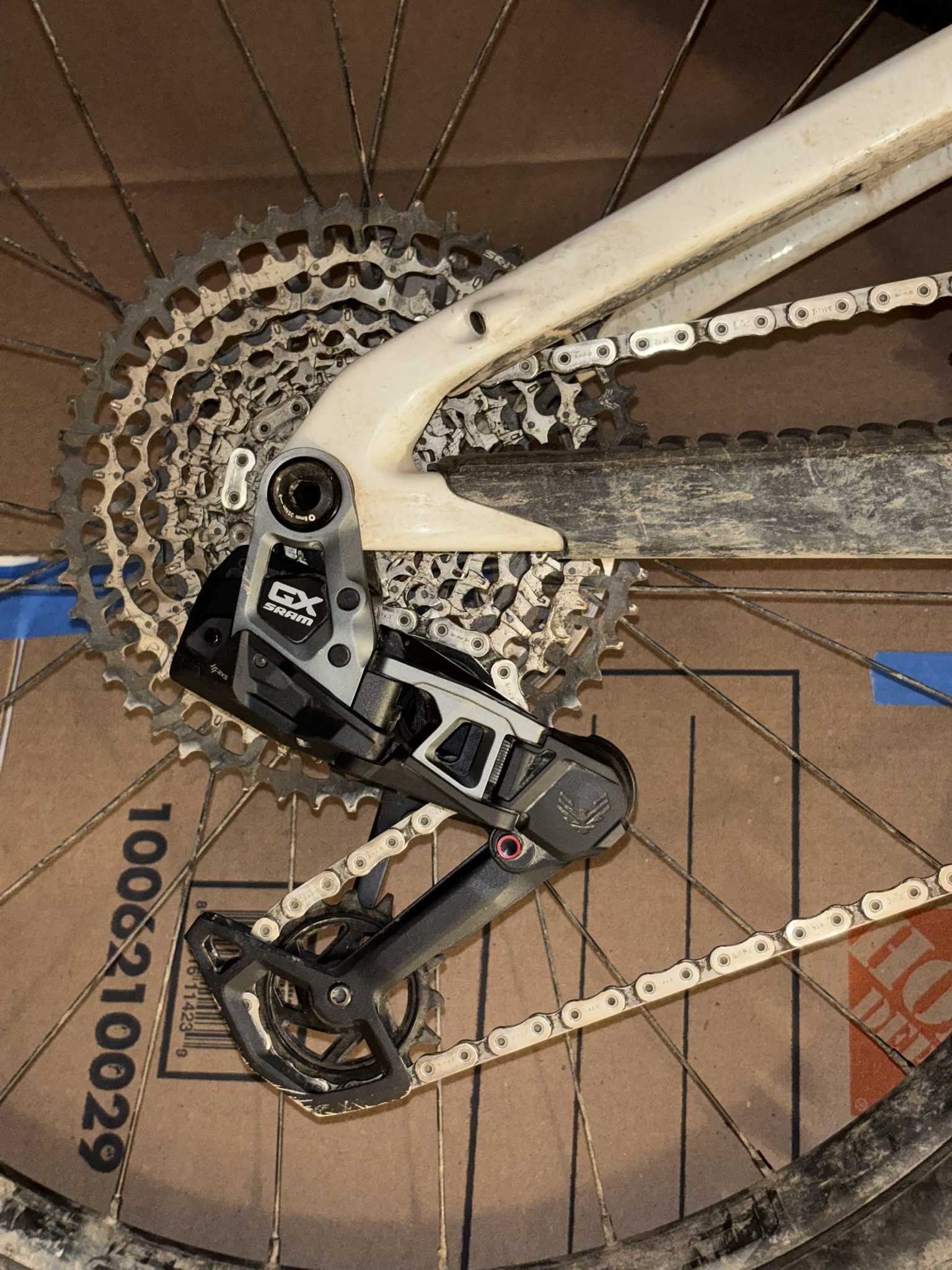 Figure 1
Failure Analysis
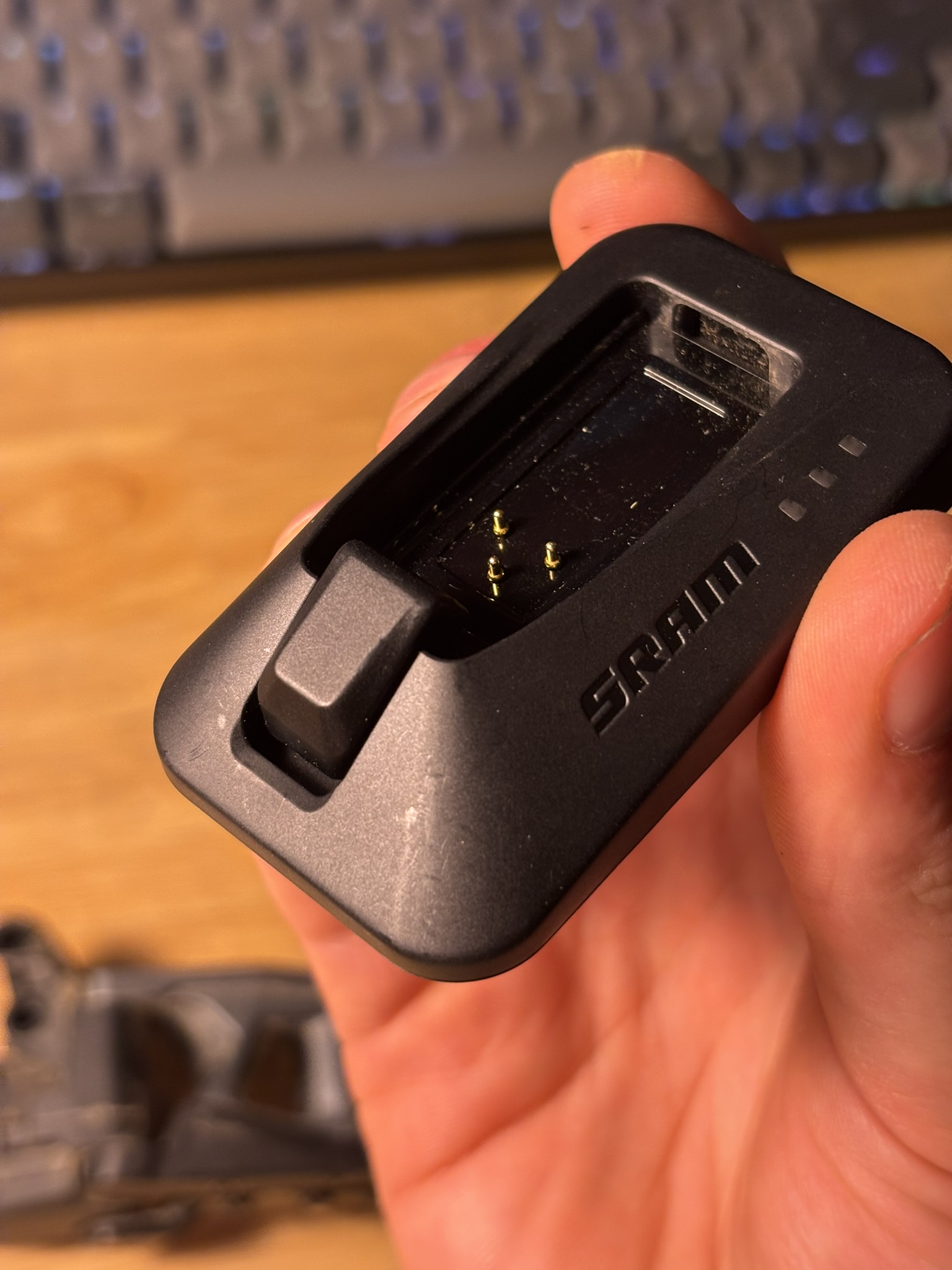
Symptoms: No power. No LED, no shifting, side button does not respond. Battery is confirmed charged using multimeter. Shifting remote pod LED is functional and pod can be connected to via Bluetooth.
Failure mode: Pogo pins fail to extend and contact battery.
Likely root cause: Galvanic corrosion between pogo pin body and spring, due to water ingress during washing. As pictured in fig. 2, there is a gasket to prevent water and dust ingress, but it does not have a strong sealing pressure, so a jet of water from a hose was the likely source of the ingress.
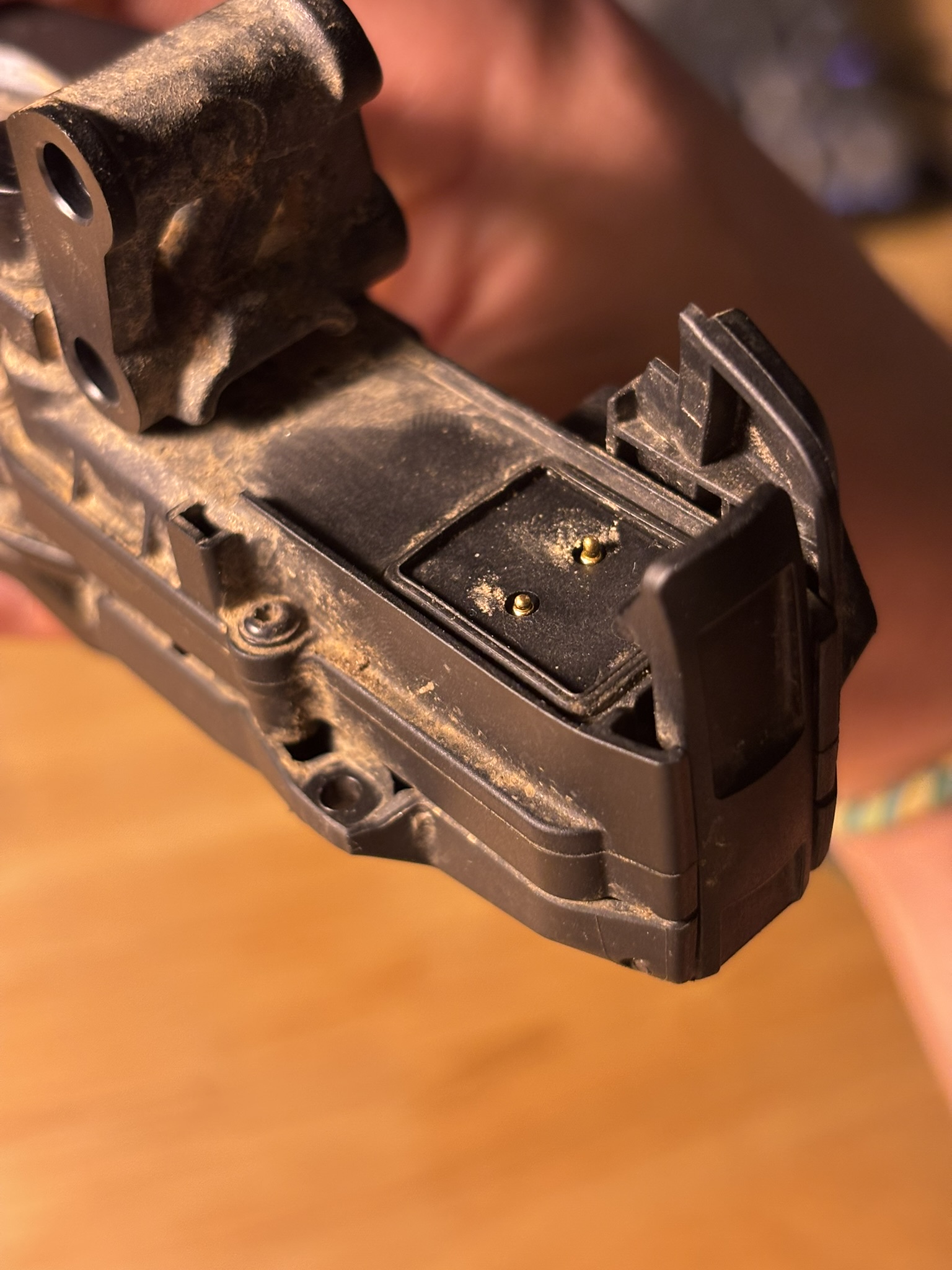 Figure 2: Faulty pogo pins
Repair
Materials Needed
Tooling
- Soldering iron >400 C
- Third hand or vise
- Tweezers
- Needle nose pliers
- Wrenches:
- Metric hex
- Metric tamper-resistant hex
- Torx wrenches
Consumables
- Solder
- Flux Optional, but recommended:
- IPA 99% w/ brush
- Light grease
- Aluminum foil or wire
Replacement Parts
- 2x 6mm pogo pins
- I sourced these from my old Sram AXS charger, because it was cheaper and faster to source a brand new charger from Amazon than it was to source pogo pins from Digikey or other similar supplier. See [[#Pogo Pin Sourcing]].
Derailleur Disassembly
- I sourced these from my old Sram AXS charger, because it was cheaper and faster to source a brand new charger from Amazon than it was to source pogo pins from Digikey or other similar supplier. See [[#Pogo Pin Sourcing]].
The derailleur requires a near complete disassembly to access the circuit board and replace the pogo pins.
- Optional, but recommended: Move derailleur to most outboard position by forcing electrical contact using aluminum foil or wire.
- The Sram process plan calls for this to take off the parallelogram, which you will need to do.
- Ensure battery is removed.
- Remove rear wheel.
- Use the derailleur lockout. Keep the derailleur cage locked for the duration of the repair.
- Remove derailleur from bicycle.
- Remove rear wheel, and uninstall derailleur from mount point.
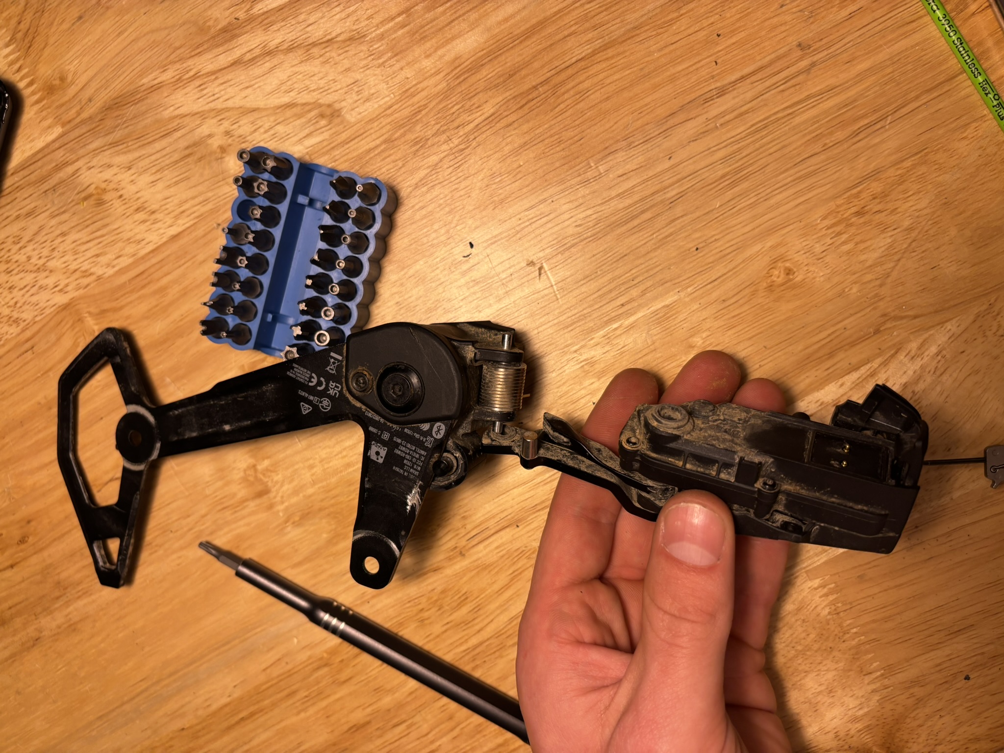
- Fully liberate the derailleur from the bike by removing the inner derailleur cage, unthreading the chain. This step either saves you $30 or fits of rage from having to do this whole repair on the bike.
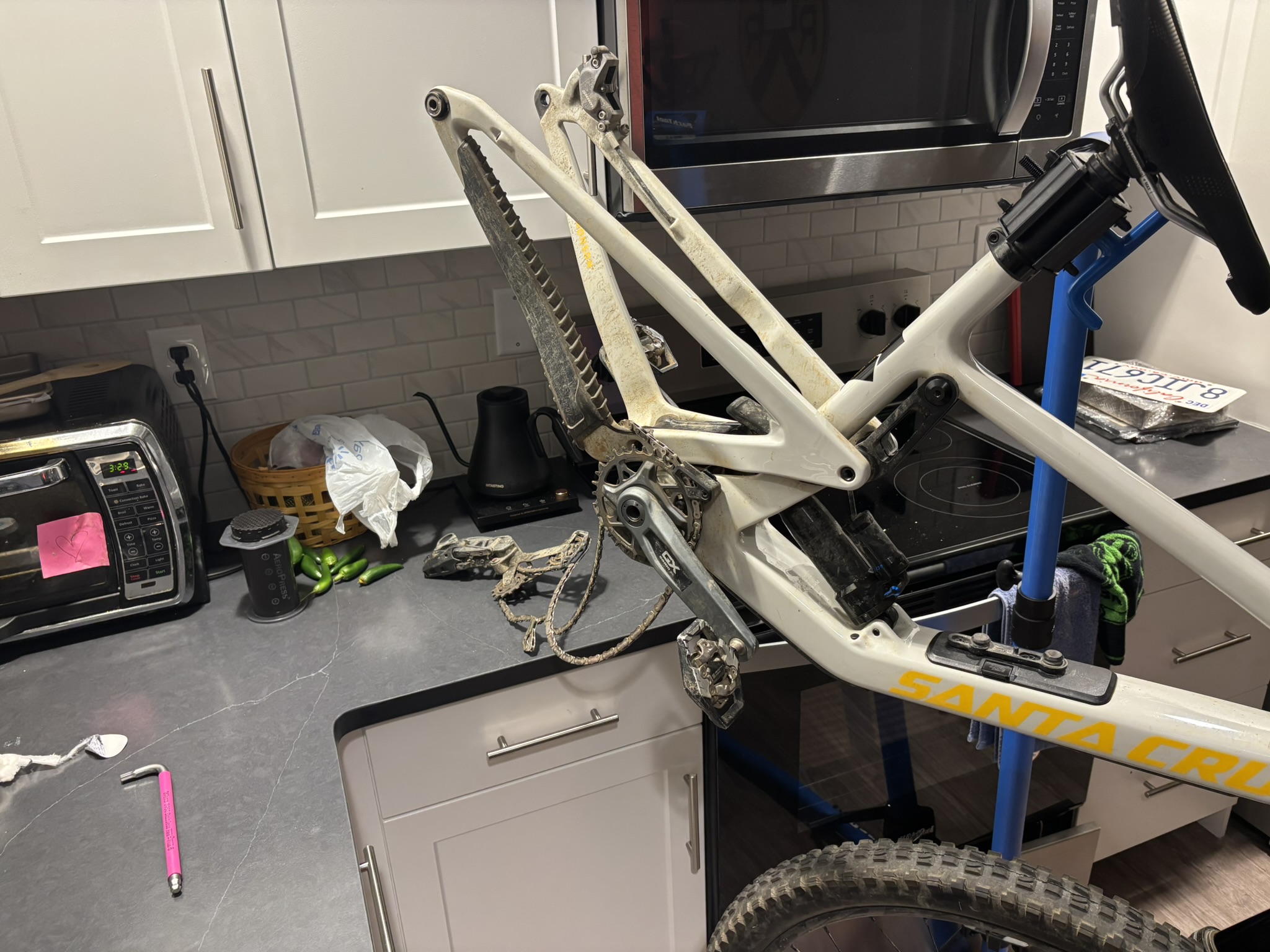 Figure 3
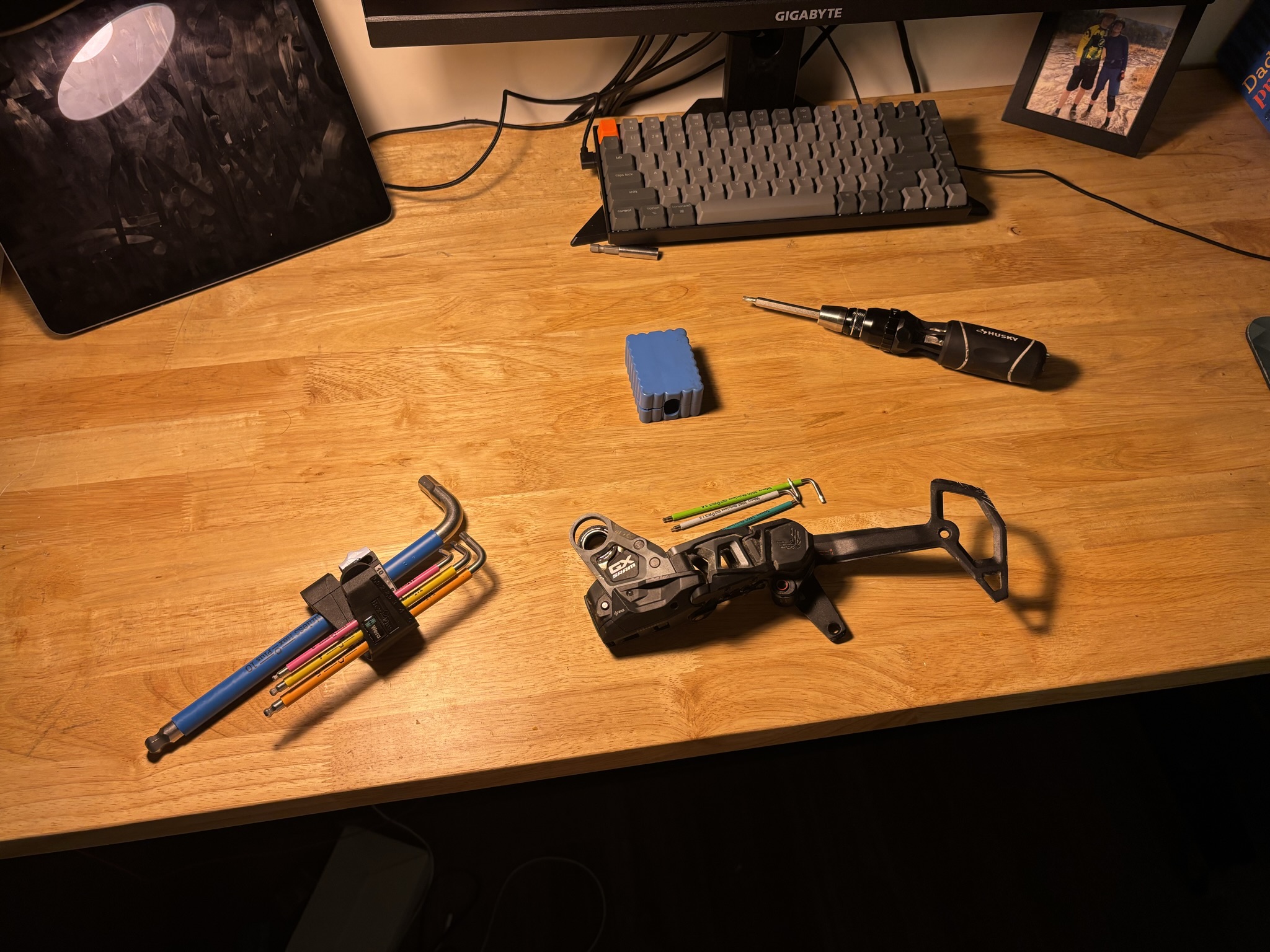 Figure 4
- Remove skid plate.
- 1x coarse pitch screw, then snap off plastic skid plate.
- It’s at this time I will inform you that this assembly is very complicated to reassemble and almost every fastener is unique. Keep everything organized: Keep fasteners with the parts they screw into. Keep parts in the same order you take them off the assembly.
- Remove both sides of the mount.
- 5x fine pitched screws.
- Don’t lose the white bushing on one of the inserts on the gray side of the mount. Its place is as pictured in fig. 3.
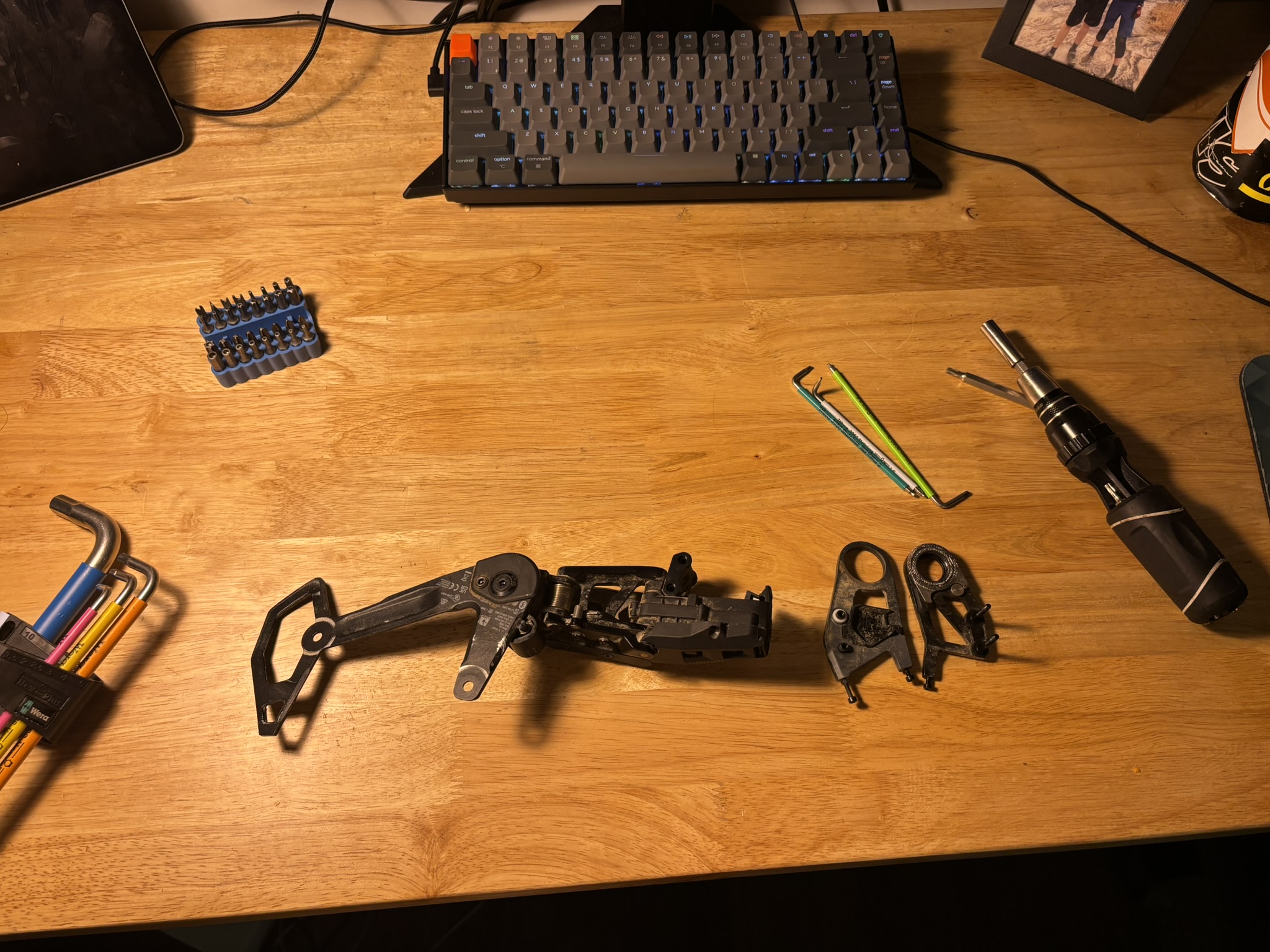 Figure 3
- Remove outer linkage subassembly.
- 2x finely pitched screws. The parallelogram linkage pivots are pins, so the top and bottom of the linkages will slide out of the pins, away from each other, after you remove the screws holding them together.
- Parallelogram linkage has a strong spring tension. Be prepared; do not pinch yourself.
- If needed use a soft pry tool to pop off the outer links.
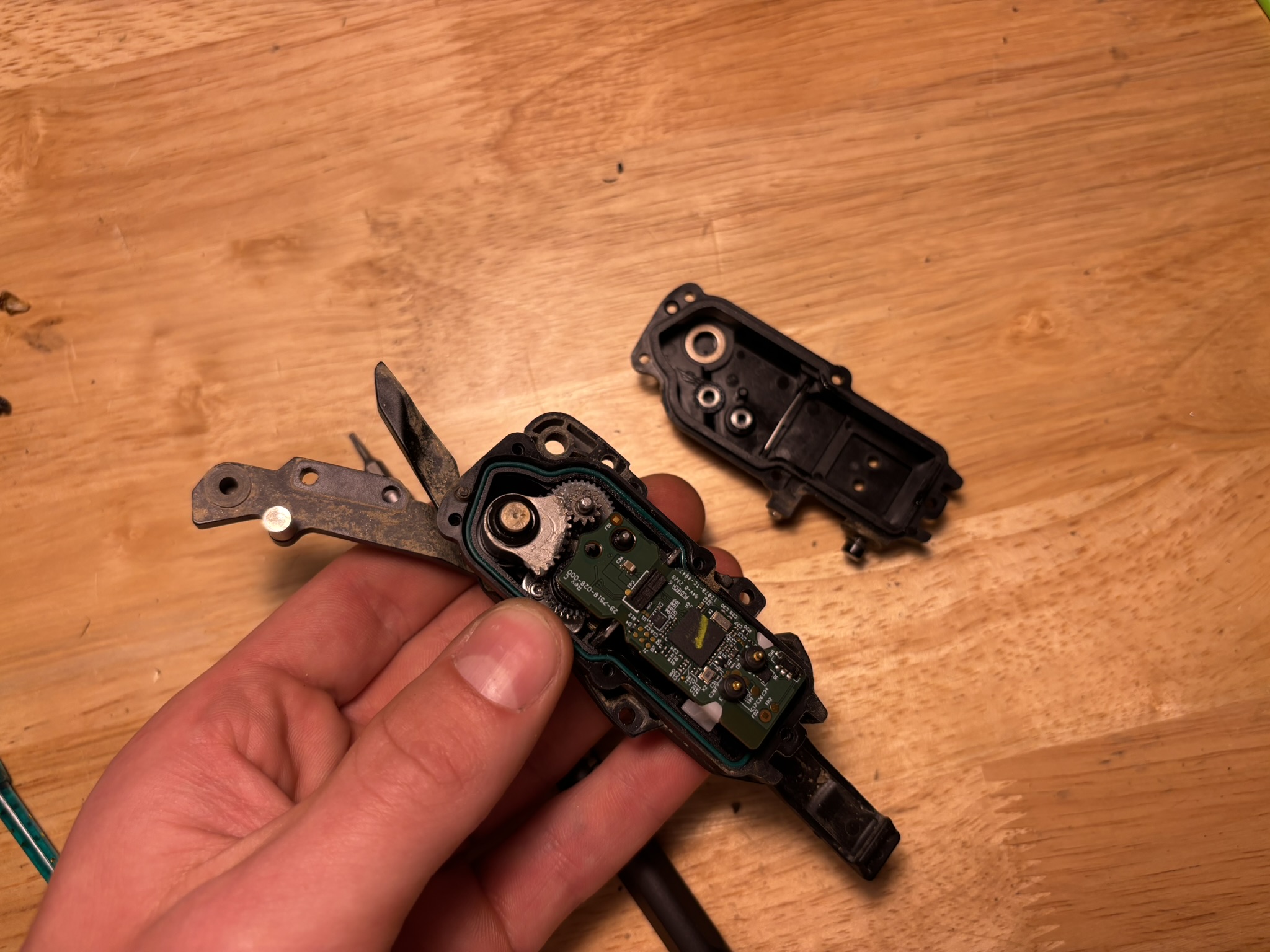
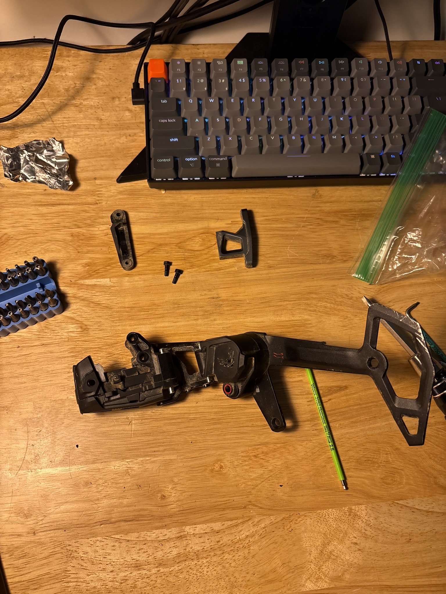 Figure 5
- Remove inner links.
- 2x Hex tamper-proof
- The inner links come off much like the outer links, but you will release the spring. It won’t come all the way undone, let it relax slowly until it contacts the electronics housing.
- The only part connected to the gearbox is the arm originating from the electrical housing, which has a groove for the spring.
- Remove the bracket covering the electrical housing with the inner/upper link.
- Remove the cage/damper subassembly.
- Remove the electrical housing lid.
- ESD sensitive operation.
- Pop off the plastic cover surrounding the button.
- 5x Torx
- Be careful to not introduce any FOD to the electrical housing gasket, or to the interior of the housing itself. Use IPA and a brush to clean if needed.
- Remove PCB from housing.
- ESD sensitive operation.
- Unplug motor wires.
- Remove white motor bracket.
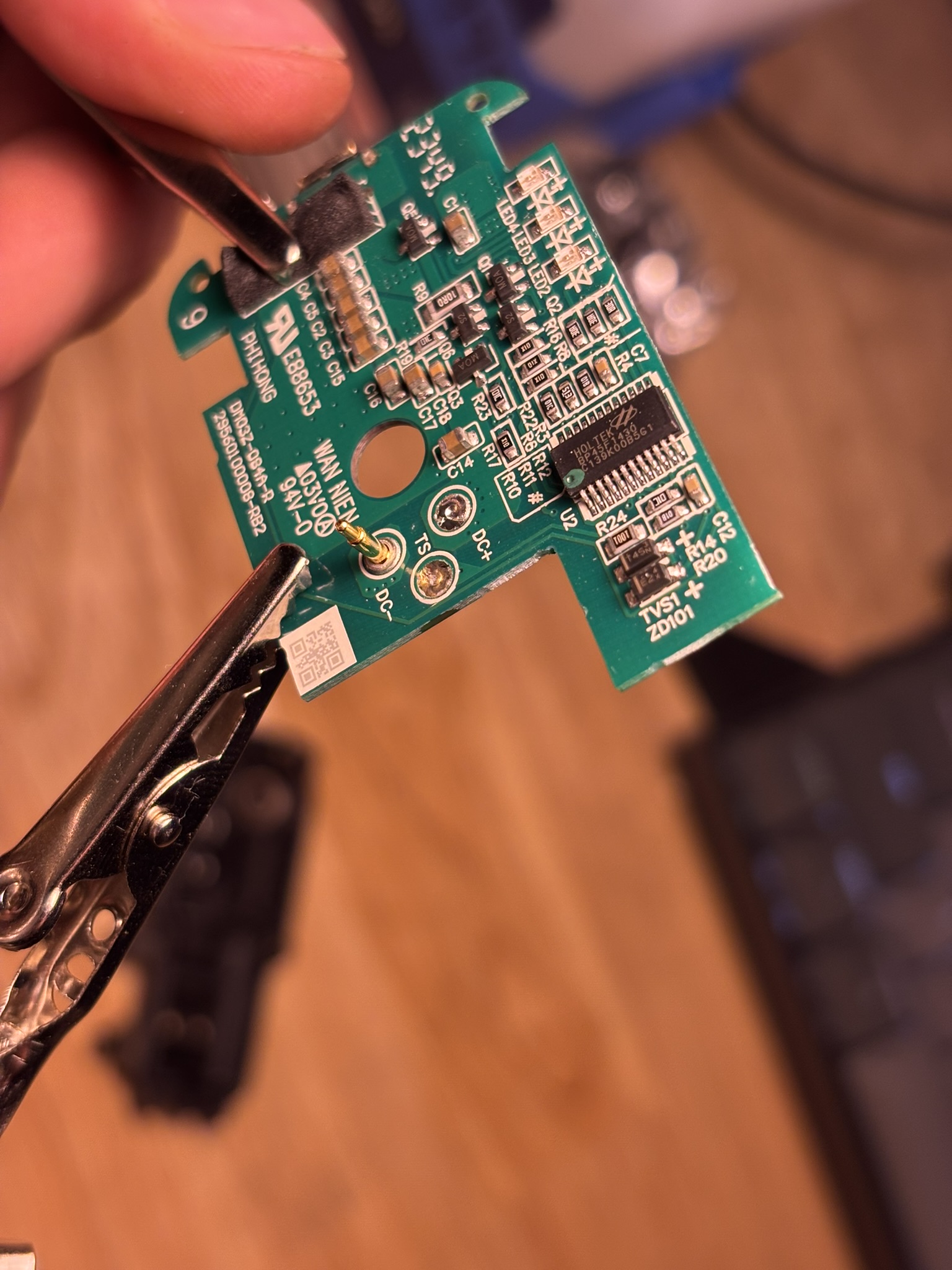
- Remove gaskets from pogo pins.
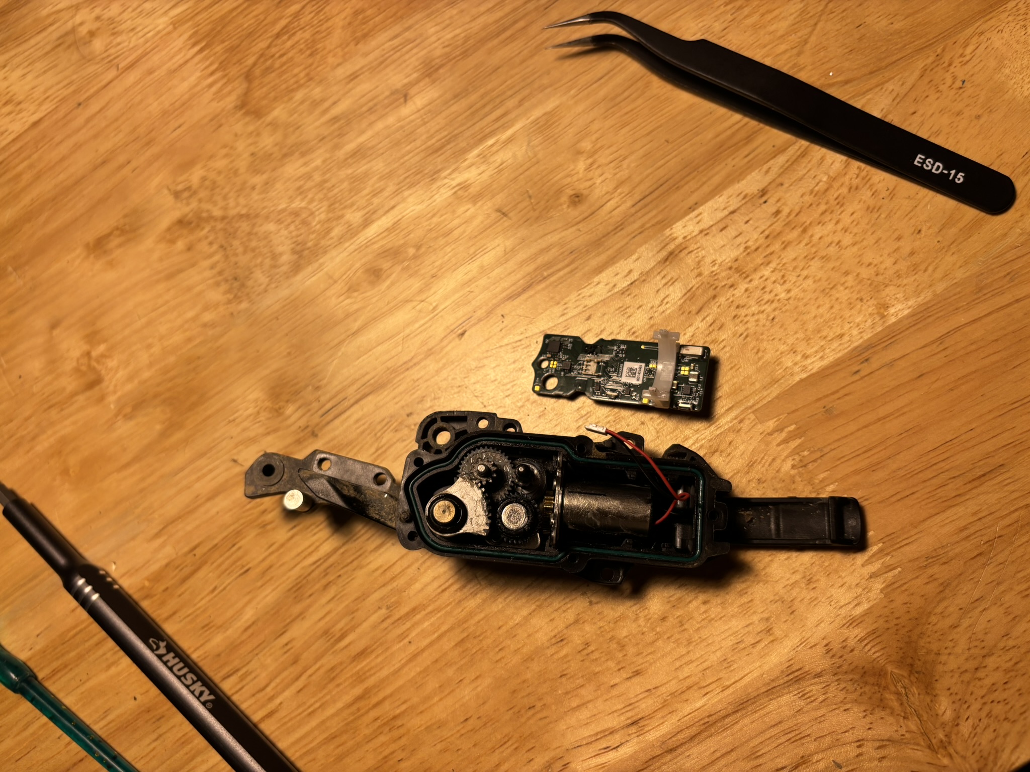
- Remove pogo pins from PCB.
- ESD sensitive operation.
- I recommend using a high temp (~380 C) to get these off. They can soak quite a bit of heat before the solder melts, especially the negative pin.
Derailleur Reassembly
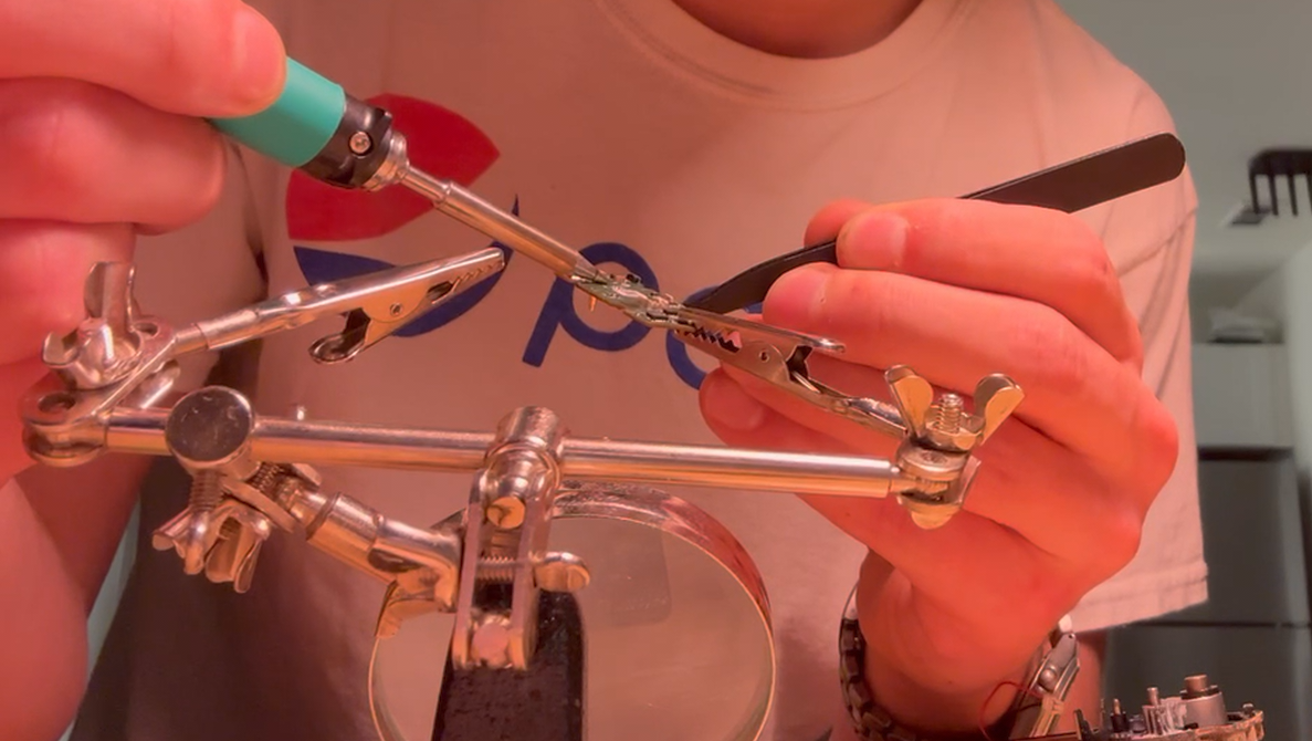
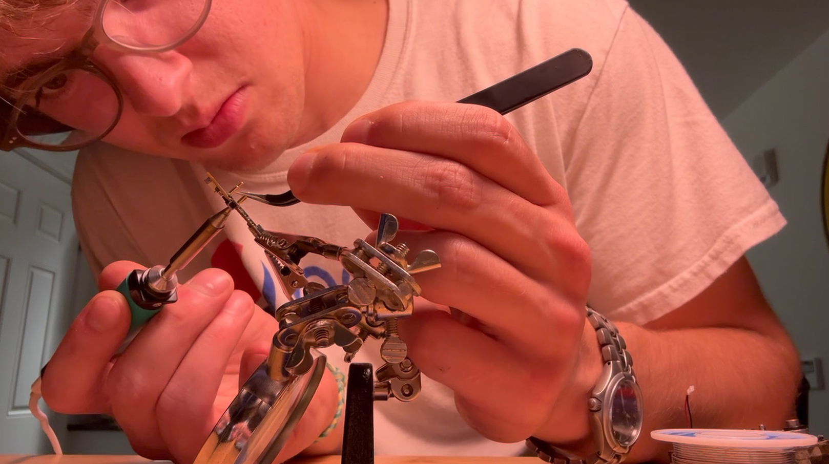
- Reinstall new pogo pins.
- ESD sensitive operation.
- Be extremely careful to get them perfectly straight. Don’t oversaturate the board with heat.
- A solid vice or third hand helps. I taped my third hand to the bench.
- Add additional solder if needed.
- Reinstall PCB & replace housing cover.
- ESD sensitive operation.
- Pogo pin gaskets, motor wires, motor bracket.
- Replace cover.
- Snap on plastic shield around button.
- To reassemble: Perform disassembly steps in reverse.
Pogo Pin Sourcing
It was cheaper and faster to source a brand new charger than it was to source two pogo pins from Digikey or Arrow. So, I ripped the pins out of this old charger: