Krakwing Build Notes
[[Krakwing Build Instructions]] [[Krakwing Board]] #rc
Build Notes
Cutting Wings
- Measured wing sides and discovered that the two edges were not parallel, with a parallelism tolerance of about 2°
- used Onshape sketcher to develop a set of dimensions to
- cut the foam to shape using the plans, mostly freehanded, with only a scale, sharpie, and calipers
- In retrospect, should have printed a template
- The wings are mostly straight, but there were some gaps that needed to be filled and one wing is ~2-3 mm “in front” of the other
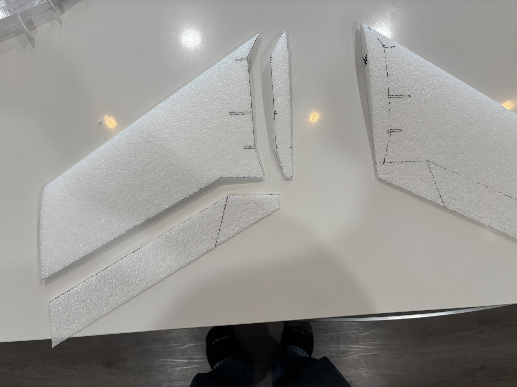 Carefully measured sharpie lines drawn pseudo-freehand
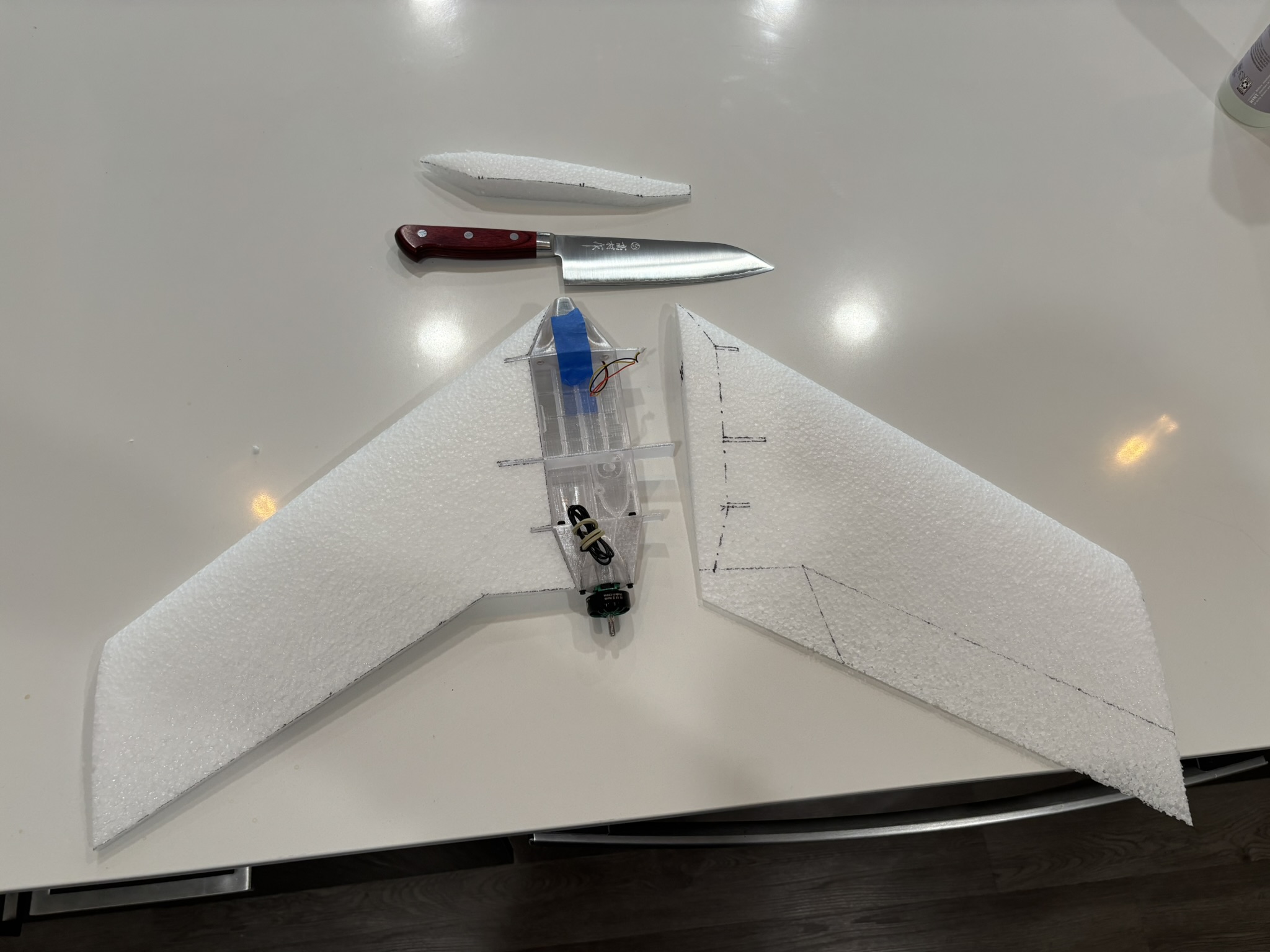 Test fitting: Yes, I cut the wings out with my Takamura.
Gluing Wings to Fuselage
Use a slower-setting glue, like E6000.
Nose
- Nose/camera mount had non-manifold geometry
- Fix: Isolate the half that had fine geometry
- For some reason, mirroring the good half would still cause non-manifold geometry on the other half
- Take that half, convert to high resolution STL mesh
- extrude cut as little as possible to make the middle completely flat
- then mirror that mesh
- final product will be a mesh that is just slightly narrower than the original (0.08mm in my case) but had fully manifold geometry
- Fix: Isolate the half that had fine geometry
- Printing was fine, I did it vertically, with tree supports holding up the camera mount and the top
- Another option was to do it on its side, with one of the wing-facing sides on the build plate
- While attractive due to needing less support, this would have led to awkward supports
- Another option was to do it on its side, with one of the wing-facing sides on the build plate
- Also had to modify the mesh to accept proper M3 threaded inserts
- The holes Daniel designed were a weird size between M4 and M3 even though he used normal M3 insert size for the motor mount
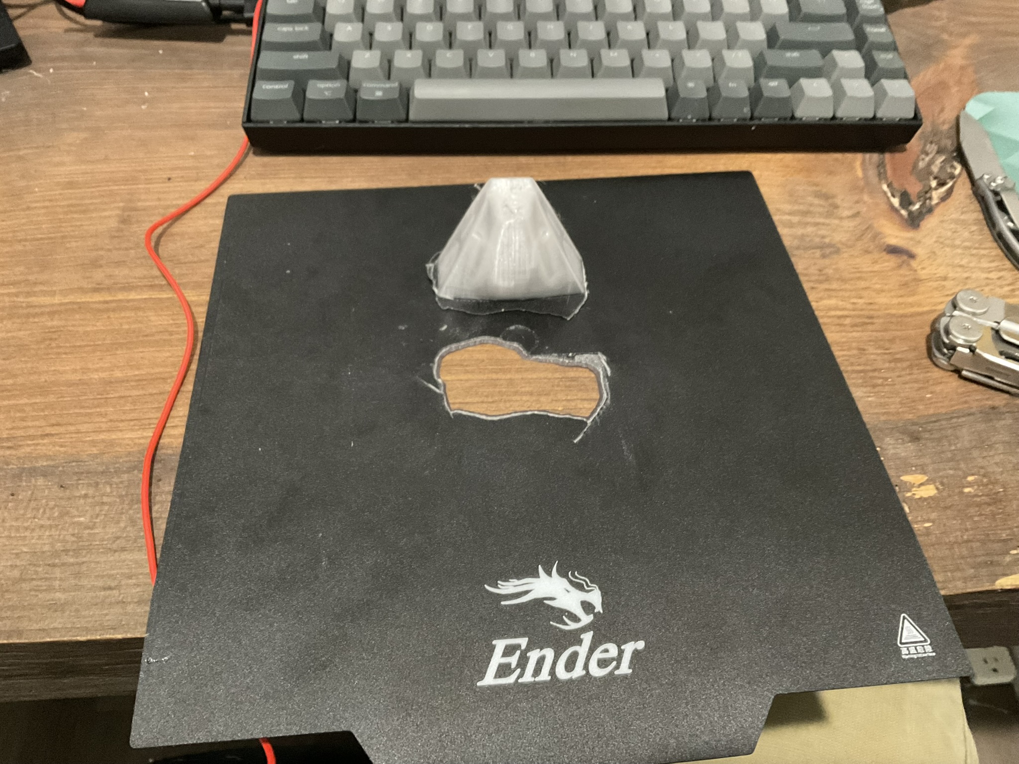
- While printing the modified heat insert version of the nose, I tore a hole in a brand new bed due to bad offsets
- After losing this brand new bed, I switched to powder coated steel and it is so much better, I should have always had a steel bed
 Nose updates 3-29:
- I thought that the FC outputted 5v to camera, but it actually outputted BV to the camera, so I fried it.
- Ordered new camera
- Will have to wire the camera to the VTx onboard 5V BEC
- I wanted to change the VTx voltage Vv on the FC to 5v, but the VTx minimum V is 7
- FC supports BV, 5V, or 6V to both the camera and VTx
Paint
- FC supports BV, 5V, or 6V to both the camera and VTx
- One coat of Rustoleum Ultracover seemed not to melt the foam noticeably
- This paint does have acetone
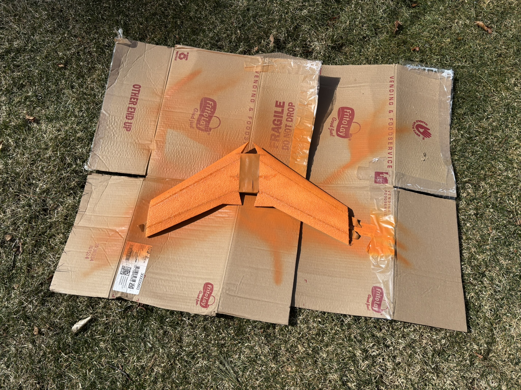
- Was a little uneven in the sunlight, but it worked out
- The paint (Rustic Orange) has a nice mellow burnt orange color
- Left the elevons unpainted
- This really gives an orange sherbet vibe to the plane
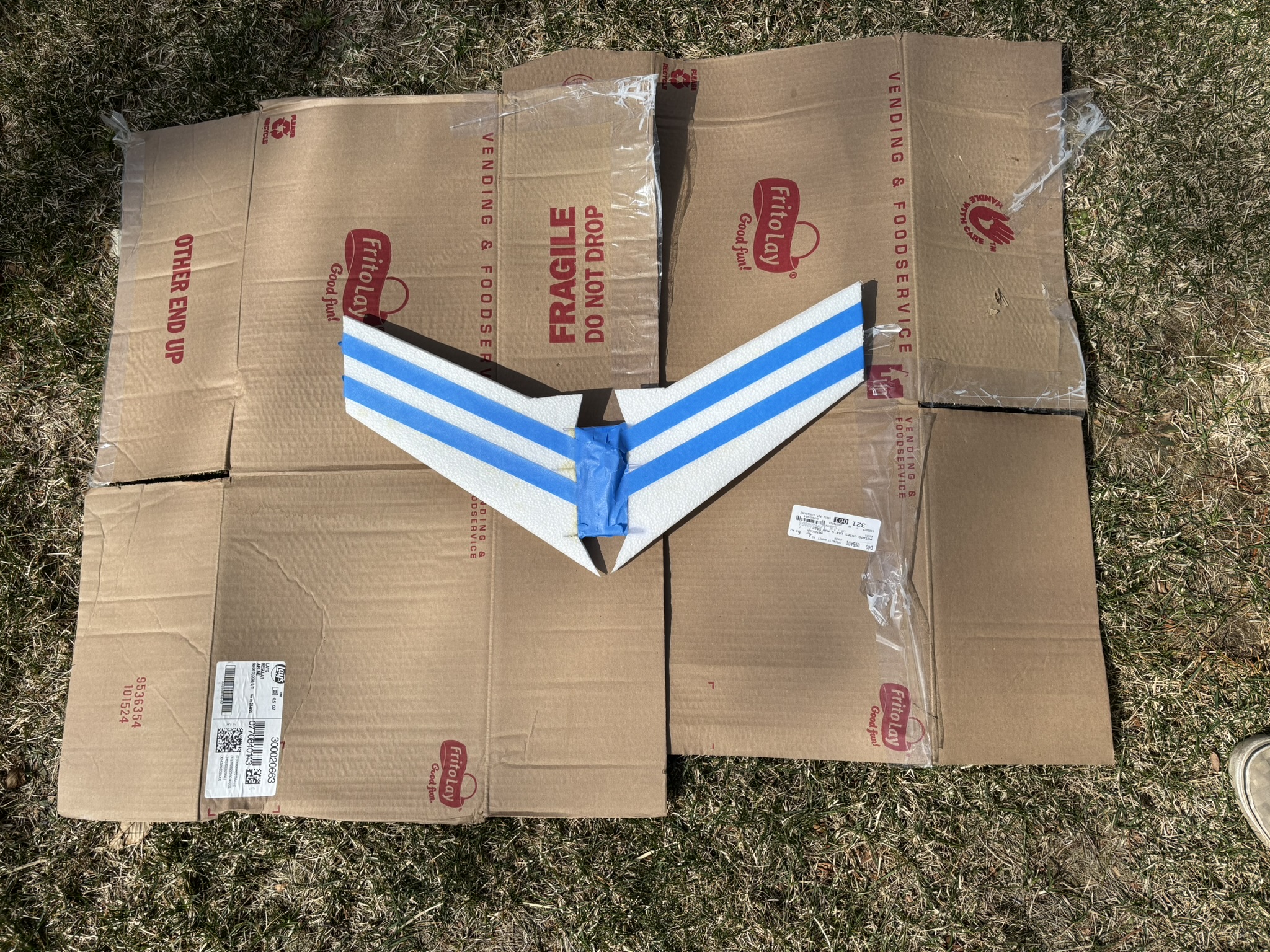
 Post-paint, pre-laminate
Foam Lamination
- Waited 24hrs from painting and that seemed to be enough time
- Sprayed the painted foam with one light coat of Super 77
- Was not enough, the laminate would stick in some places but not in others, most importantly the corners
- didn’t notice the foam being dissolved
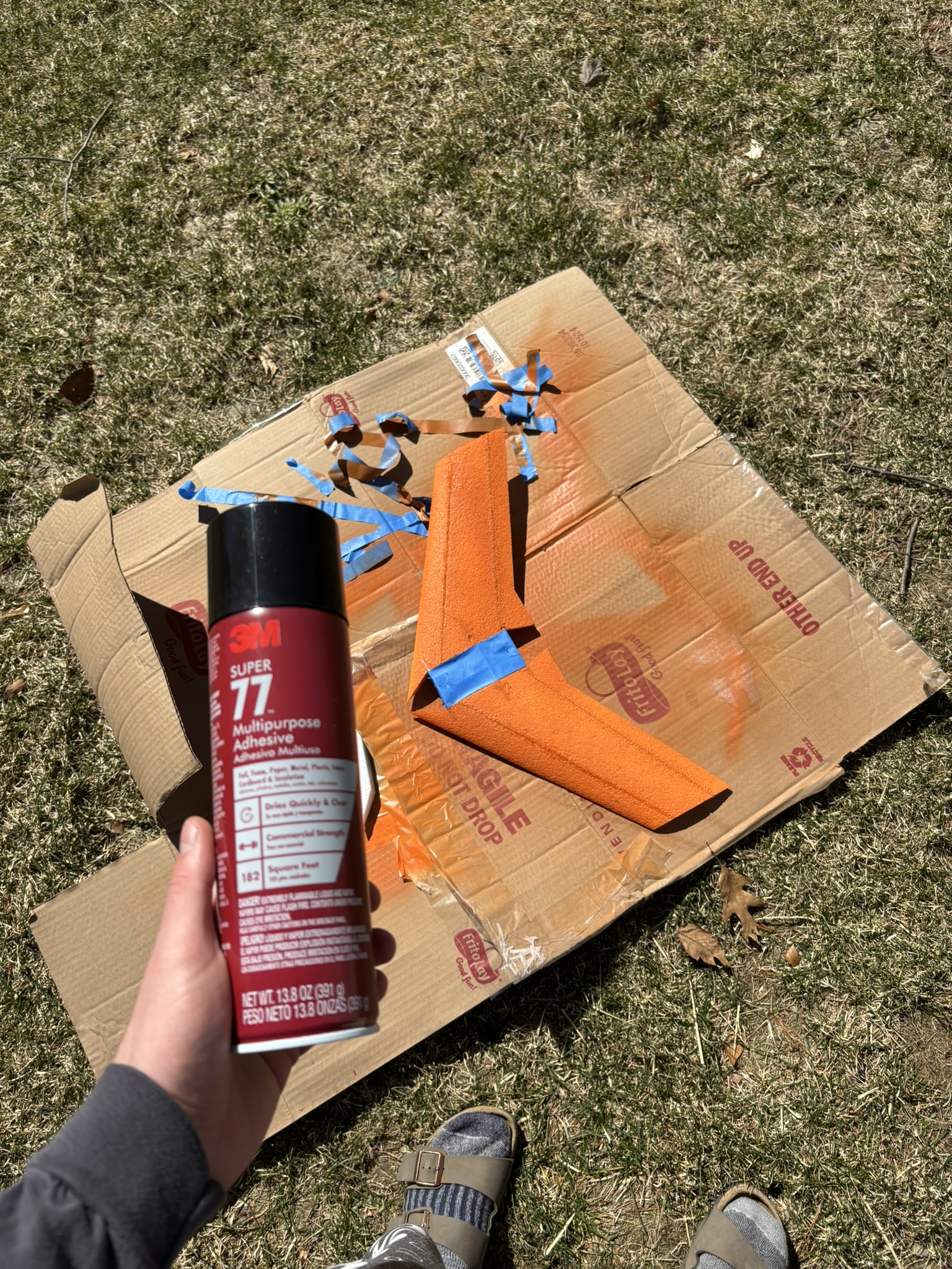 Super 77 is almost completely transparent
- Cut the laminate to shape
- One piece for each piece of foam
- Using a Black & Decker nonstick clothes iron from Amazon
- No water
- setting 4 “blends” was too hot
- setting it right above 3 (synthetics) to 3.5 seems to be right, will depress the foam only just slightly at 2-3psi
- Tried two methods: pinning down corners and ironing from center out
- With this film (I don’t know what it is, but I think it’s stationery laminate) the center-out method worked better: there were less wrinkles. Was not able to eliminate wrinkles entirely, however.
- Cut off excess film, will cover the beveled edge with a small flap
- Overlapped foam from the top side to the bottom, i.e. left a flap on the top and ironed it over the bottom
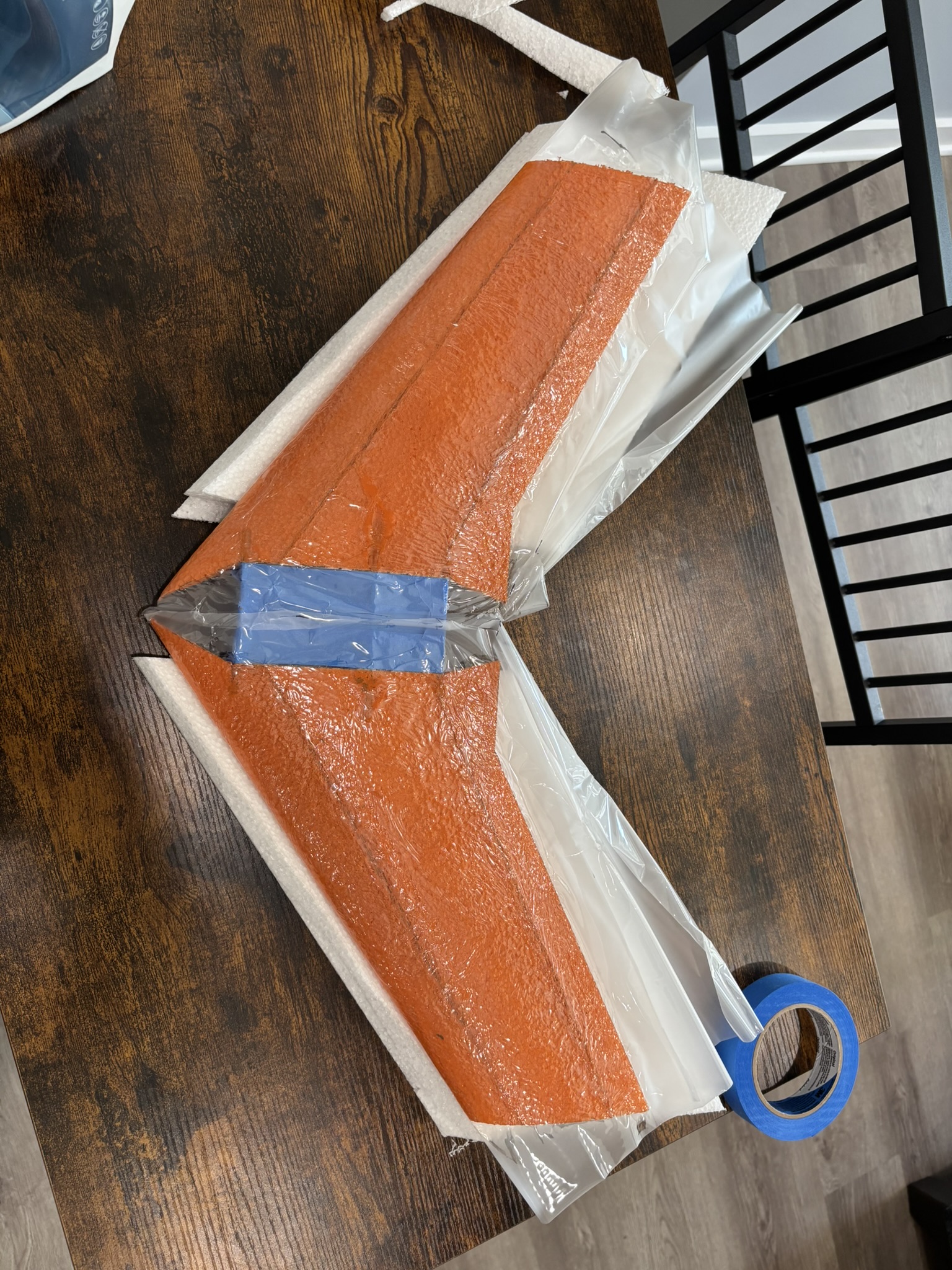
- The laminate shrunk ever so slightly
- It was enough to deform the slight reflex in the control surfaces, but this was to be expected because of how thin they are
- Cut off excess with a utility blade
Attaching Elevons
- Used 3M standard packing tape
- cleaned the surfaces with 99% iso
- carefully attached elevon (the tape sticks to laminate, not foam) top surface first
- Maximum deflection during sticking to ensure that the elevon has enough range of motion
- Bottom surface then taped, also at max deflection
- Cut the excess tape away from the edges
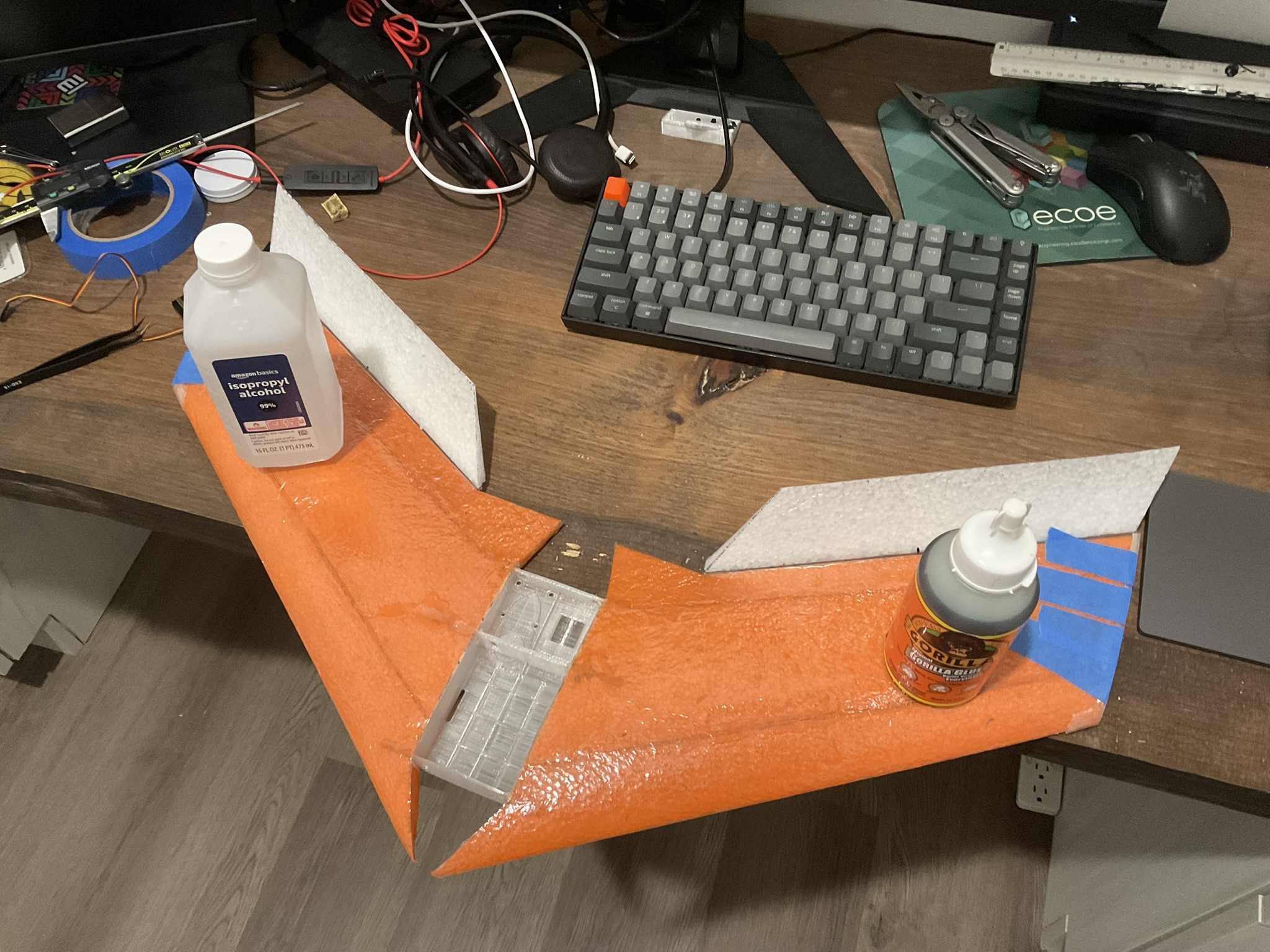
Wingtip Covers
- Used a sharpie to mark where the holes in the covers were on the foam
- had to expand the holes with a knife
- Used foaming gorilla glue and used tape to clamp the covers onto the wings
- I have previously noticed that Gorilla glue soaks into the foam, so I hope that these will actually adhere
- They seem to have adhered great with only small dots of Gorilla glue in a line spaced about 10mm apart
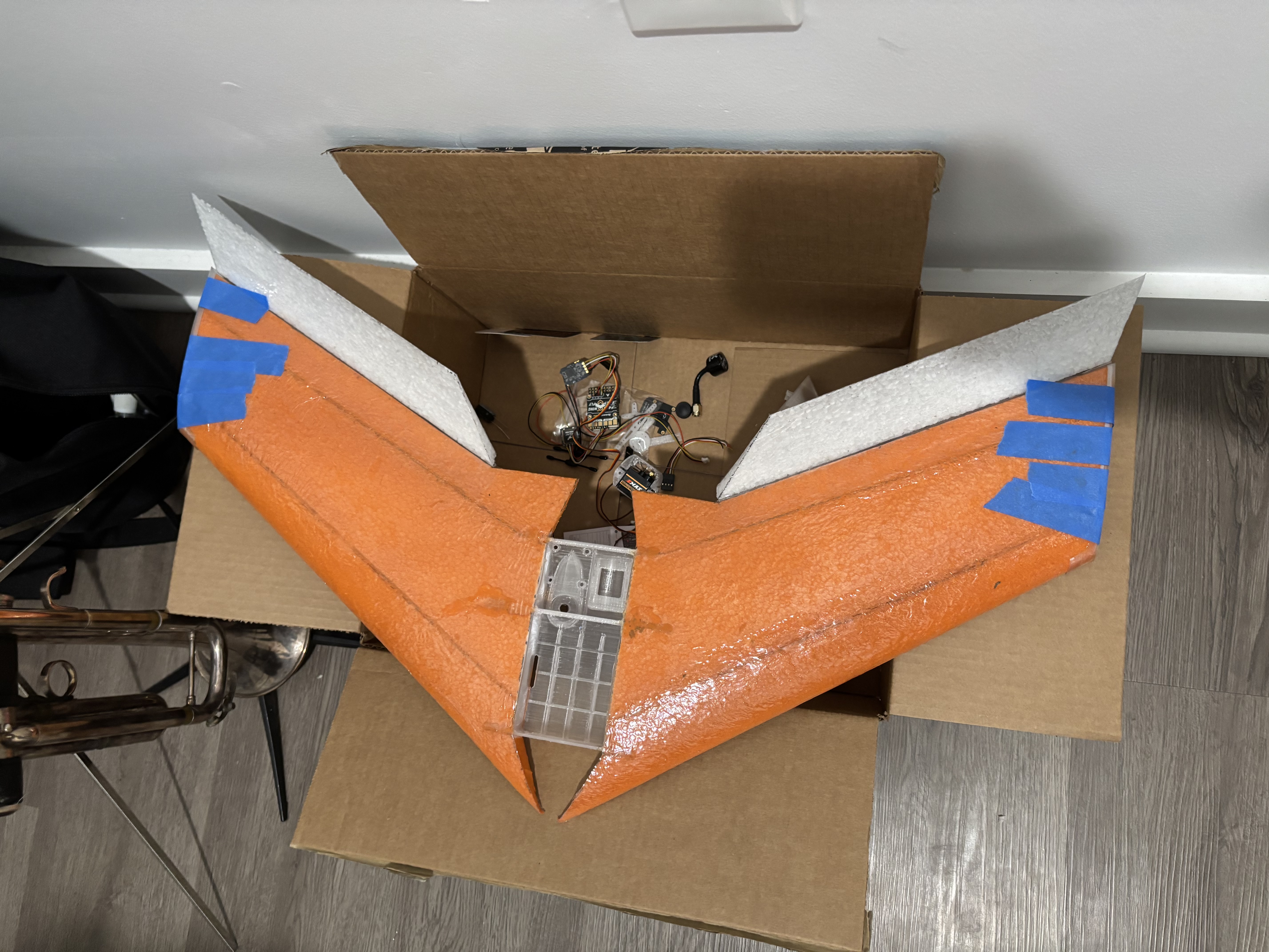 Here, the tape on wingtips is to clamp on the wingtip covers while the glue cures
Servos pt. 1
- I am personally soldering the servo wires onto the flight controller because the DuPont connectors are too tall for the plane and horizontal connectors wouldn’t fit in the avionics compartment
- Traced in the servo housings 5mm back from the main spar
- Cut the traced lines with a utility knife, going roughly the depth of the servo housing (~15mm)
- picked out the foam beads with pliers for big chunks and tweezers for individual beads
- Glued in the servo trays
- Spread glue around the sides of the tray
- One thin bead around the whole thing was a good amount: only got the slightest bit of foaming through the top
- The sloppier side (I tried to smear this side) got a little glue that dripped underneath the tray, but no big deal. A thin bead around the bottom edge of the side was plenty.
- Used small bottles to weigh down the trays overnight
- They seem to have stuck great pre-flight
- Spread glue around the sides of the tray
At this time, I have to think critically about where I will route the servo wires, because I plan to have some electronics out on the surface of the wings, so I’m going to continue the servo story in the next section.
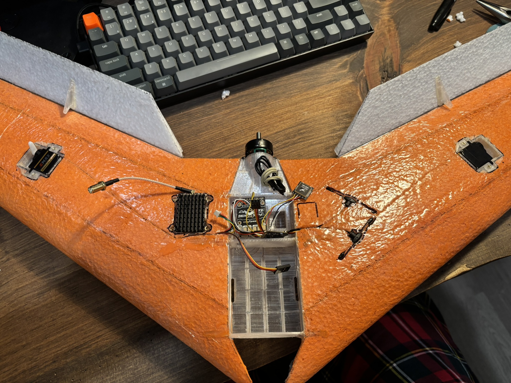
Electronics Placement
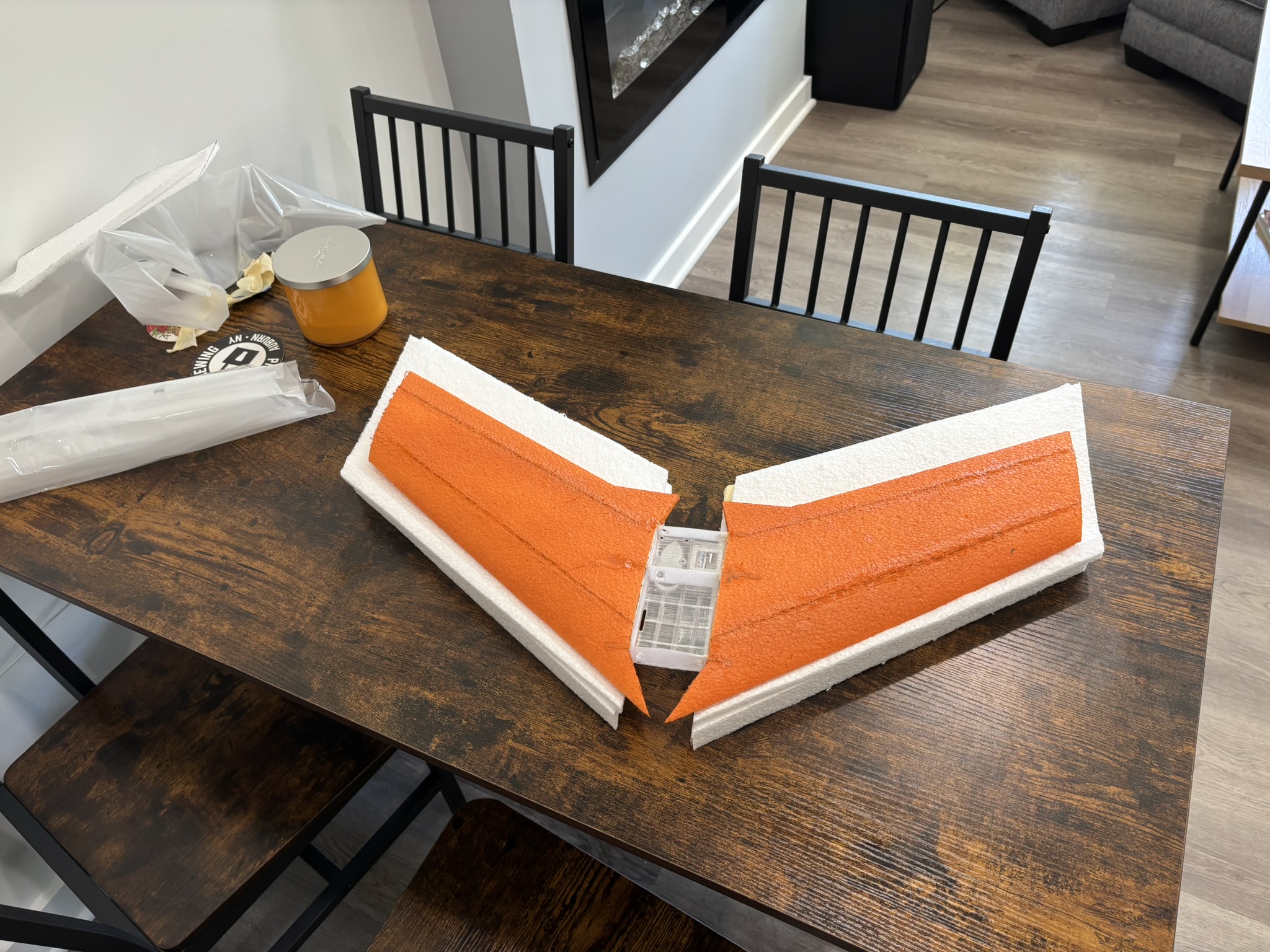
I didn’t modify the avionics bay. I really thought I would have this project done in a weekend, and I didn’t want to wait for another to print. In retrospect, I definitely should have waited and modified the avionics bay.
Since I decided to buy different electronics than Daniel designed the plane for, they don’t really fit well in the avionics bay. I bought all of these right when the news outlets were crying “tariffs” and I really thought I would be hit hard if I tried to buy the Daniel-configured electronics from Aliexpress. So, I Amazon Primed slightly a different controller and VTx. The controller is smaller, but it doesn’t line up with the 3d printed holes. The VTx is bigger, so I will have to mount it on the wing. This is not a huge deal though, as I can use the empty space in the avionics compartment for the receiver and ESC.
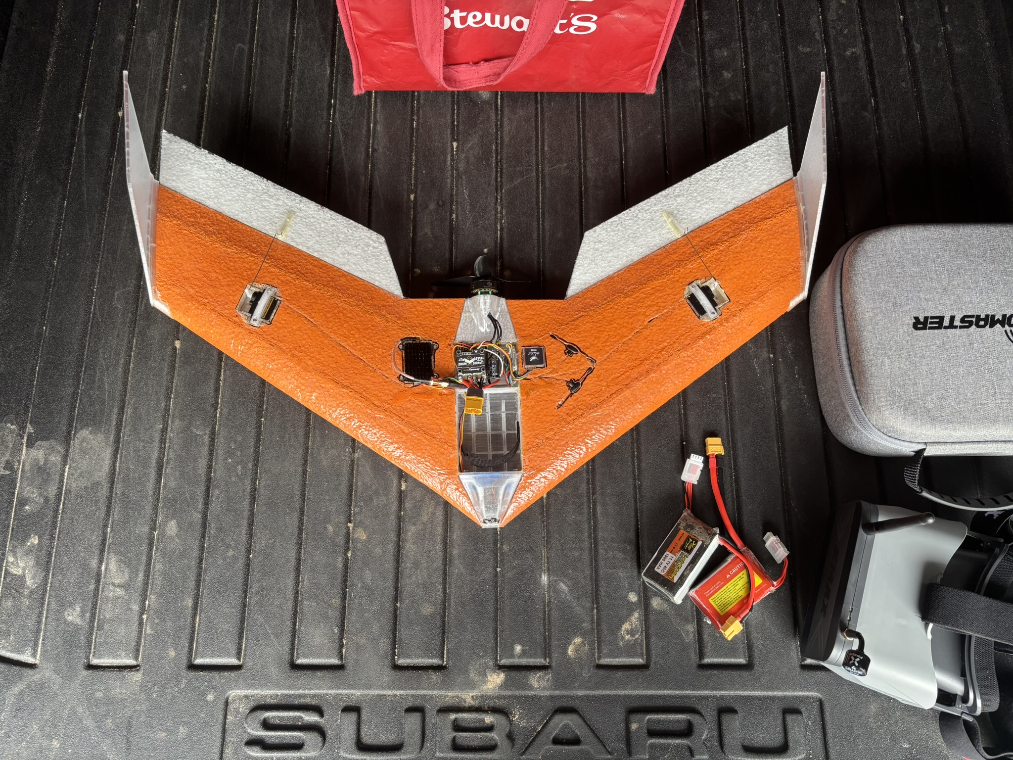
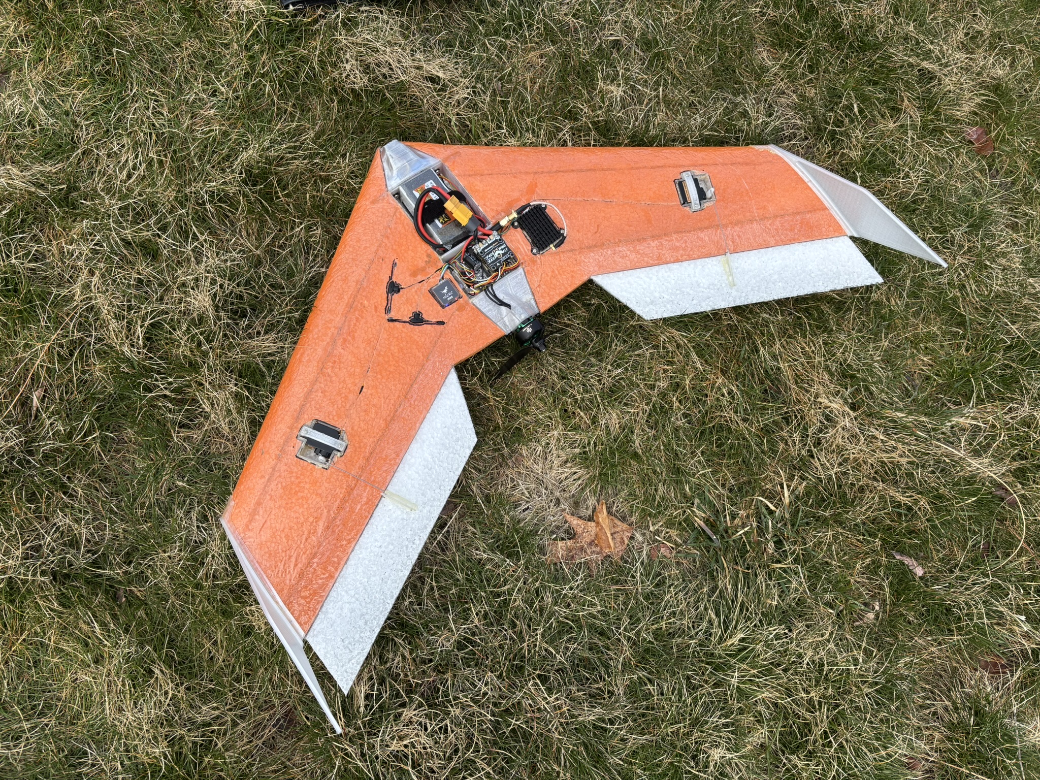
Conclusion
It flies!